![]()
What are Electrical Transformers? [with Diagrams]
DISCLAIMER: AS AN AMAZON ASSOCIATE I EARN FROM QUALIFYING PURCHASES. THIS POST CONTAINS AFFILIATE LINKS THAT WILL REWARD ME MONETARILY OR OTHERWISE WHEN YOU USE THEM TO MAKE QUALIFYING PURCHASES. FOR MORE INFORMATION, PLEASE READ MY EARNINGS DISCLAIMER.
The word Transformer means to transform or to change so these are used to change the AC voltage levels. The use of transformers is very common. We can find numerous appliances which include transformers in their circuitry. For example, in our homes, we use computers, amplifiers, stabilizers, mobile phone chargers, etc. all contain transformers.
A transformer is comprised of two coils. These coils are wounded on a single iron core and are electrically insulated from each other. The coil which is used as input is referred to as a primary coil and the coil on the output side is called the secondary coil. Each coil has a specific number of turns according to the specific voltage requirement.
- Number of turns of primary coil= “NP “
- Number of turns of secondary coil = “NS “
- The voltage of the primary coil = “VP “
- Voltage of secondary coil = “VS “
- Current of primary coil = “IP “
- The current of the secondary coil = “IS “
In transformers, the changing current flows through the primary coil it also produces changing magnetic fields around the primary coil. As the primary and secondary coils are wounded on the same core so this changing magnetic field also flows through the secondary coil and e.m.f. (electromotive force) or simply the potential difference or voltage is induced in the secondary coil.
When this secondary coil is connected to the external load, the current begins to flow. This is the principle of mutual induction and also the basic principle of working of transformers.
The core of the transformer is made from special material which allows more magnetic flux to pass and in the meanwhile produces less heat. Also, it is made in laminations which reduces the load losses and eddy current losses in the transformers.
The basic formula on which a transformer is designed is the turn ratio formula:
Can a transformer operate on Direct Current (D. C.)?
No, a transformer cannot operate on a Direct Current (DC) because the direct current is a constant current with zero frequency. To induce the e. m. f. on the secondary side of the transformer we need a changing magnetic field or flux.
A constant current like in Direct Current (DC) cannot produce the changing magnetic flux. So no current will produce on the secondary side when we connect the transformer to a Direct Current (DC) source.
A transformer can only operate when it is connected to the Alternating Current (AC) source.
Types of Transformers on the Basis of Voltage Level
The two main types of transformers which are based on voltage levels are step-up transformers and step-down transformers.
1. Step-Up Transformer
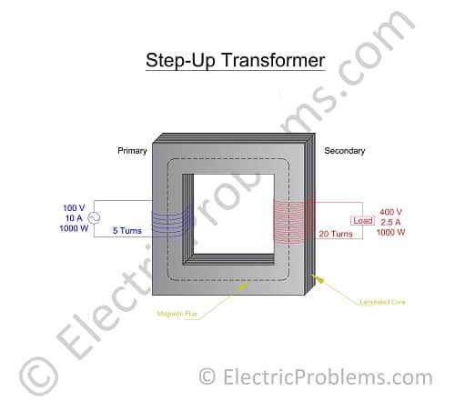
If the voltage of the secondary side is greater than the voltage of the primary side, then the transformer is referred to as a step-up transformer:
Step-up transformers are used at the generating stations. Generating stations are located in faraway places from the consumers of the electricity. The transmission from the generating station to consumers is done at a very high voltage.
So at the power generating stations, the step-up transformers are used to increase the voltage level.
Feel free to download this Step-up transformer diagram in PDF format for a closer look.
2. Step-Down Transformer
If the voltage of the secondary side is lower than the voltage of the primary side, then the transformer is referred to as a step-down transformer:
Step-down transformers are used at the consumer’s side. The power gained from the transmission lines is at a high voltage which is decreased by step-down transformers so that a consumer can get electrical power at a normal voltage level.
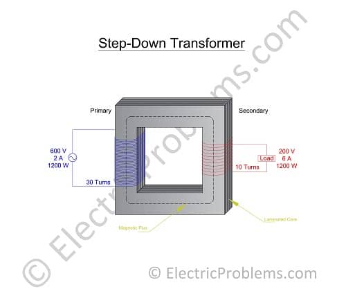 This step-down transformer diagram can also be downloaded in PDF format. Both transformer diagrams in one PDF file can be downloaded here.
Interesting Question
In the case of the step-up transformer, the voltage of the secondary side is greater than the voltage of the primary side. For example, if we are giving 100 V to the primary side of the transformer as input and the transformer is giving us 400V on its secondary side as output then from where this extra voltage comes.
The answer is in the below discussion.
Power in The Transformers
From the point of view of the power, we can separate the transformers into two kinds:
- Ideal transformers
- Practical transformers
1. Ideal Transformers
In an ideal transformer, the power which we give to the transformer on the primary side is equal to the power of the secondary side. This means no loss takes place in the transformer.
The answer to the above question is that as:
As power is a constant factor in the above equation so if the voltage is increased then the current is decreased.
2. Practical Transformers
The transformers which are used around the world are not ideal as there is a small loss of power in the core etc. So the power on the secondary side or output power is always less than the power on the primary side or input power.
Types of Transformers on the Basis of Working
We can categorize the transformers on the basis of the work they do:
1. Power Transformers
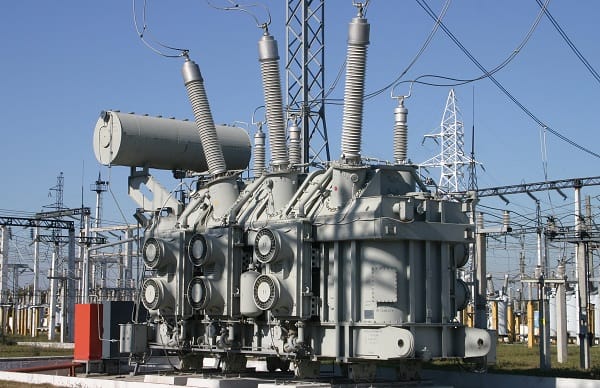
These transformers are used at the generating stations to step up the voltage level and at the transmission substations for step-down the voltage level. These are huge in size.
The typical ratings of power transformers are 400kV, 200 kV, 110 kV, 66 kV, 33 kV. These standards may vary from country to country.
2. Distribution Transformers
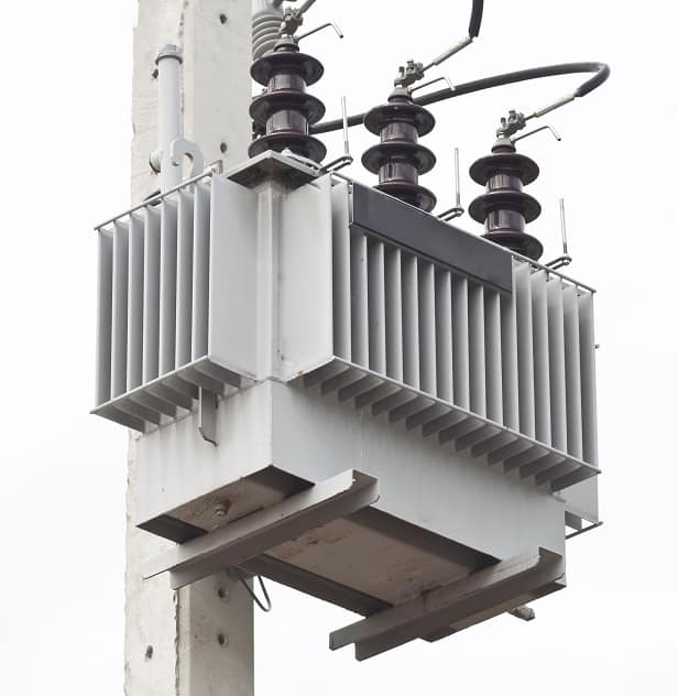
These transformers are smaller in size than power transformers. These transformers take input from the transmission substation and provide power to the local consumer.
The typical ratings of distribution transformers are 11kV, 6.6 kV, 3.3 kV, 440 V, 230 V. These standards may vary from country to country.
3. Instrument Transformers
While working with AC we often need to measure the quantities like current, voltage, power, power factor, energy, and frequency in a circuit. These quantities can be easily measured with instrument transformers.
We just need to use the correct type of instrument transformers and wire them properly. Instrument transformers come in two types: current transformers and voltage transformers.
- Current Transformers
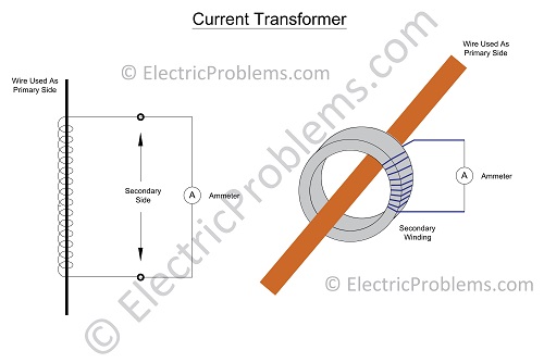
Current transformers (C.T.) are used when we have to measure a high value of current in a circuit like transmission line etc. The heavy current line or the transmission line acts as the primary coil and we have a suitable number of turns on the secondary side.
This transformer reduces the value of current to an extent that can be measurable by an ordinary ammeter as proportional to the actual current in the transmission line. We can use them as:
And we can find the current on the secondary coil as:
 Here is a schematic representation of the current transformer:
Feel free to download the PDF file of the picture above.
- Potential Transformer or Voltage Transformer
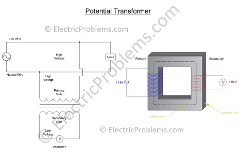
Similarly, as the current transformers, a potential transformer (P.T.) is used whenever we need to measure the high voltage level with an ordinary voltmeter. Actually, this is a step-down transformer that reduces the primary high voltage to a safe value to be easily measurable by a simple voltmeter.
Secondary voltage is in proportion to the primary voltage. Here is a schematic for a potential transformer:
Here is a PDF file to download for greater detail.
Single Phase Transformers
As the name indicates these transformers have only one phase, and the other wire indicates the neutral wire. These transformers can operate both as step-up and step-down transformers.
These kinds of transformers are mainly used in home appliances to step down the voltage level from 110 V to 12 V.
Three Phase Transformers
Download PDF file here.
These transformers use three wires in three different phases indicated as three colors, on the primary side. In the USA for low voltage, these are Black, Red, and Blue and for high voltage, these are Brown, Orange, and Yellow.
They can also be used as step-up and step-down transformers.
Feel free to comment below if you have any questions. Here is a file of ALL schematics mentioned above in PDF format.

Click on the white button above to find your electrician!


