
![]()
How to Wire an Inverter in an RV [Schematics in PDF]
DISCLAIMER: AS AN AMAZON ASSOCIATE I EARN FROM QUALIFYING PURCHASES. THIS POST CONTAINS AFFILIATE LINKS THAT WILL REWARD ME MONETARILY OR OTHERWISE WHEN YOU USE THEM TO MAKE QUALIFYING PURCHASES. FOR MORE INFORMATION, PLEASE READ MY EARNINGS DISCLAIMER. |
When choosing your wiring setup, just make sure that your inverter does not end up powering your converter-charger. Professional installation is highly recommended and advised!
So, you got a brand new inverter for your RV and now it’s time to wire it! Here is a good explanation on connecting your inverter to RV’s electrical system (and below I will include some diagrams to look through):

![]()
Now, we are going to discuss the step-by-step wiring procedure of an RV.
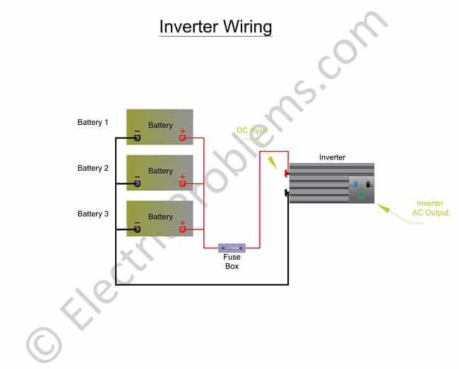
Inverter Wiring
The inverter is a device that converts Direct Current (DC) to Alternating Current (AC). Let’s discuss a simple example in which an inverter is connected to a battery bank.
Feel free to download the PDF version for greater detail.
In the above diagram, three batteries are connected in parallel to each other and power up the inverter’s DC terminals. A fuse box is installed on the positive (red) wire.
If we connect high capacity and a greater number of batteries to the battery bank, then the time for which we can take power from the batteries is increased. The inverter then changes the power to AC, which is collected from its AC output socket.
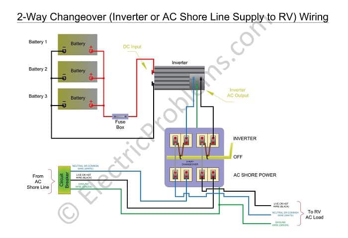
2-Way Changeover (Inverter or AC Shore Line Supply to RV) Wiring
2-Way changeover is a switching circuit that changes the output power between two inputs like in this case between the inverter and AC shore power line. The 2-way changeover switch shown in the below diagram is a manual changeover switch. It can be purchased from the market at a very cheap price.
The power from the AC shoreline is coming through a circuit breaker. The inverter’s live and neutral wires are connected to one of the input terminals of the 2-way changeover switch, while the AC shore power line is on the other input terminal.
The AC load of RV is connected to the output terminals of the 2-way changeover switch. The ground wire is connected to the ground terminal or the body of the 2-way changeover switch.
 The Pdf version is available here.
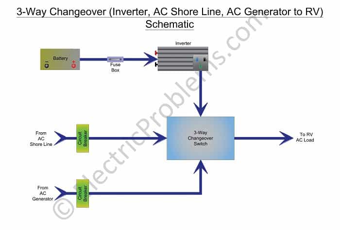
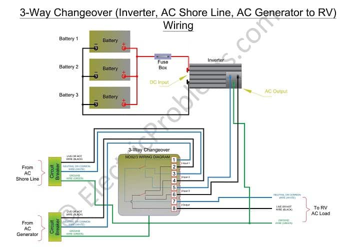
3-Way Changeover (Inverter, AC Shore Line, AC Generator to RV)
The 3-way changeover switch changes the output between three inputs, in this case, we connected the power from the AC shoreline to input 1, the AC generator to input 2, and from the inverter to input 3. We can connect the output to any of these inputs by toggling the switch. The output terminal is further connected to the RV AC load.
The power from the AC shoreline and AC generator are coming through their respective circuit breaker. The 3-way changeover switch shown in the below diagram is a manual changeover switch of a specific company, model number is written on the diagram. You can use any changeover switch and wire it up on the same lines.
 |  |
Here is a schematic diagram in PDF and this is a wiring diagram in PDF.
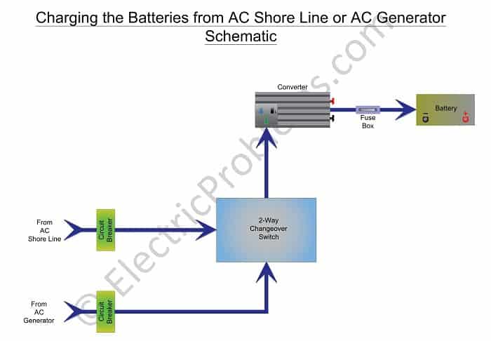
Charging the Batteries from AC Shore Line or AC Generator
RVs have a battery bank which is used to power the RV appliances. For charging these batteries, the schematic and wiring diagrams are shown below.
Here we can use a 2-way changeover switch. We can take power either from the AC shoreline or the AC generator. AC shoreline is connected to input 1 and the AC generator is on input 2 of the changeover switch.
The output of the changeover switch is further connected to a converter. A converter is a device that changes the power from Alternating Current (AC) to Direct Current (DC). In order to charge the batteries, we have to connect Direct Current (DC) source to the batteries. Thus a converter serves this purpose. A fuse is installed on the positive (red) wire for safety requirements.
 | 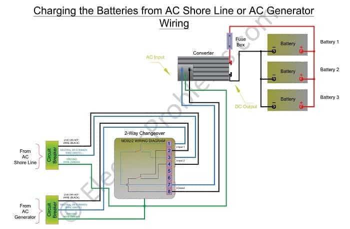 |
You can download a PDF version of this schematic here and here is a wiring diagram in PDF as well.
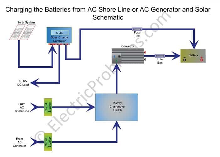
Charging the Batteries from AC Shore Line or AC Generator and Solar
We can charge the batteries from the solar system. The schematic and wiring diagrams are shown below.
The solar plate’s output is connected to the solar charge controller. From the solar charge controller, we have an option to connect the RV DC load. The solar charge controller is further connected through a fuse box to the battery bank. The fuse box is installed on the positive (red) wire.
In these diagrams, we have three options to charge the battery bank. These are AC shoreline or AC generator and solar system.
 | 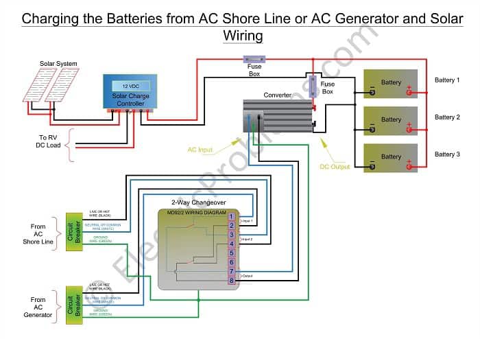 |
Here is a schematic in PDF for this diagram and this is for the wiring diagram (also in PDF).
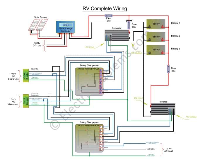
RV Complete Wiring
Now we are in a position to discuss the whole RV wiring. In this section, we connected all the above circuits together.
The battery bank is charging from the solar system as well as from converter output. The converter can run from either the AC shoreline or from the AC generator. Both sources can be changeable through a 2-way changeover switch.
On the AC output side, a 3-way switch is installed which have three input options
- From AC shoreline
- From AC generator
- From AC output of inverter which is taking power from the battery bank.
The output of the 3-way changeover switch is connected to the AC load of the RV. The DC load of the RV is connected to the solar charge controller. All the appliances in the RV should be connected in parallel to each other and to the source of the Alternating Current (AC).
 |  |
Here is complete RV wiring in PDF (schematics & wiring). And in this file, you will find ALL the schematics together.
How to Select an Inverter for RV?
RV (or a Recreational Vehicle) is a type of vehicle that can also be used for living purposes. These types of vehicles are mostly used for recreational purposes and usually have a set of 12-volt batteries or a solar system installed (12 VDC).
An inverter is used to turn a 12-volt power supply (that is coming from either batteries or solar) into 110 VAC in the USA (or 220 VAC in some other countries). After installing the inverter in our RV, we will be able to use home appliances (like TV, electric kettle, hairdryer, etc.) that work on the AC power supply.
There are basically three inverter types and they differ according to the output wave they produce:
1. Pure Sine Wave Inverters
If we analyze the output of this kind of inverter through an oscilloscope, then we will find that the waveform of output is like a graph of ![]() .
.

This kind of output provides clean AC power to the devices and does not damage them. These inverters are more expensive than other types that I will be discussing later. It is the same power type that we get from utility companies or from standby generators.
2. Modified Sine Wave Inverters
The output of this kind of inverter is NOT a pure sine wave. Its waveform has corners and edges rather than around and smooth lines. It looks more like steps:

These inverters are cheaper than pure sine wave inverters and do not supply clean power to the devices. The devices run on this kind of inverters might produce a little noise.
3. Square Wave Inverters
The waveform of these inverters, when hooked up to an oscilloscope shows an even bigger difference from a pure sine wave. Its values have an abrupt change from their maximum value to the minimum value. This is what it looks like:

This is the cheapest form of inverters that can cause damage to the devices. Appliances produce even greater noise when run on square wave inverters (than on modified wave).
Keeping in mind the above types, we can select an inverter by taking into account our budget and the devices to use. One more thing which needs to be resolved is the power of the inverter.
To find the power of the inverter, we have to know that how many devices we are going to run on the inverter. Let’s take an example, we want to run a T. V, an electric kettle, and a microwave oven. Then we have to find the power of each device and add them up.
The total value of power in Watts will be the required power of the inverter:
One T. V. (LCD/LED) = around 100 Watt
One electric kettle = around 1200 Watt
One microwave oven = around 1000 Watt
Total Power = 2300 Watt
Different models of each device can have different power consumption. The power consumption of each device is written on its manual/brochure.
In our example, the maximum power is 2300 Watt. We can find an inverter in the market which has a higher power rating than our calculation. We can select a 3000 Watt pure sine wave inverter of any company for our RV.
Here is more information on upgrading your inverter/converter system to an inverter-charger (Replacing the RV Converter with Inverter Charger).
Our Team

Legal Disclaimer

