![]()
How does a Rotary Phase Converter Work?
DISCLAIMER: AS AN AMAZON ASSOCIATE I EARN FROM QUALIFYING PURCHASES. THIS POST CONTAINS AFFILIATE LINKS THAT WILL REWARD ME MONETARILY OR OTHERWISE WHEN YOU USE THEM TO MAKE QUALIFYING PURCHASES. FOR MORE INFORMATION, PLEASE READ MY EARNINGS DISCLAIMER.
A Rotary Phase Converter is designed to create three-phase power from a single-phase power source. Unlike a Static Phase Converter (that only STARTS a three-phase motor), a Rotary Phase Converter will RUN your equipment continuously and get to its full horsepower potential.
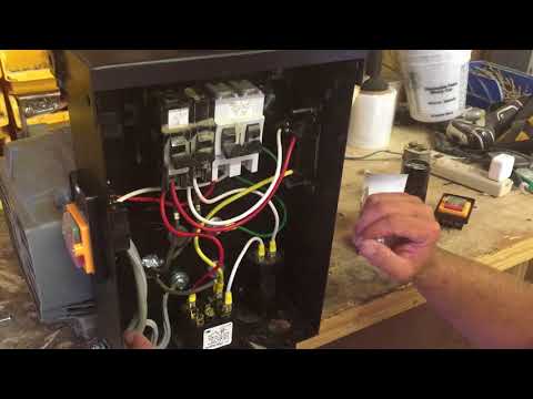
The rotary Phase Converter system is made up of an idler generator and a control panel. Your start capacitors and run capacitors go inside this control panel, as well as any of the switches and relays.
By hooking your 3-phase motor to an idler generator and capacitors, you will get a 3-phase power source even though only 1-phase power could be coming from your utilities. Your idler needs to have at least a 20-30% higher HP rating than the motor that you are trying to run.
So, how do Rotary Phase Converters work? Single-phase power energizes a three-phase idler generator by giving it two legs’ worth of power. Start capacitor will give the idler motor a third leg to get it working and a run capacitor will balance the phases out in order to provide your motor with a clean and reliable 3-phase power.
Rotary Phase Converters working
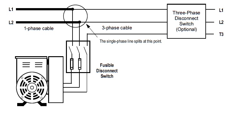
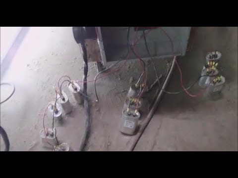
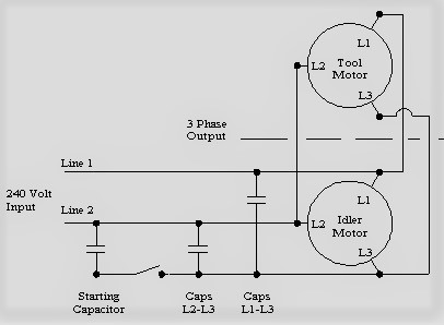
Rotary Phase Converter is made up of a 3-phase idler generator (or motor without external shafts), and a bank of capacitors wired together to work as a single large capacitor. Here is the schematic diagram:
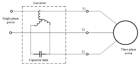
From the diagram, you can see that the converter is receiving power from a single-phase two-line power supply (to produce two-thirds of the phases required), and the Rotary Phase Converter creates the third line of power.
Rotary Phase Converter’s idler motor needs a boost (a third leg) in order to get going. This can be done by some kind of another mechanical device (another motor, for example) or the use of the capacitor’s provided rotating magnetic field to start the converter (also known as start capacitors).
Once running, the three-phase idler motor will run on two legs of a single-phase power supply and generate the third phase in the process. This will give our equipment 2 phases from utilities and one phase from the third leg of the motor winding.
These three lines will be connected to our three-phase machine motor and it will start and run just as it would on three phases from the utility company. Run capacitors need to be sized properly as well in order to supply perfectly balanced 3-phase power at 120 degrees.
To operate Rotary Phase Converter, you will need to start it WITHOUT any connected load and once it starts producing power, connect your largest motor first. It can also work through the distribution center to give your whole shop three-phase power.
Three-phase motors are considered to be more efficient than single-phase, this is why they are a preferred option for shop or factory owners. So, how do 3-phase motors rotate? Here is a good explanation (video):

Here is a continuation of the above video on how to do Rotary Phase Converters work:
https://www.youtube.com/watch?v=eXS9ahNzds0&t=3s
![]()
For those who need more details about how 3-phase power works, I recommend watching a video below from The Engineering Mindset:
![]()
If you are into building electrical devices, I will include some videos on that, below. For those that are just getting started, don’t forget that:
Working with electricity is dangerous!
** Warning! Do not attempt to do anything if you don’t have enough knowledge and training!
Here is a nice video on how to turn a single-phase power source into 3-phase power:
Here is another interesting video on how to build Rotary Phase Converters:
If you are building a Rotary Phase Converter yourself, there is a big challenge, that you get to face like – phase imbalance.
If your phase voltage variation exceeds:
4 %
… you can damage your equipment. This is where Run Capacitors come into play. Your phase-degree separation is supposed to be at 120 degrees.
Here is some information (with calculations) on balancing run capacitors:
![]()
You will also need a Starting Capacitor if you don’t want to manually spin idler your motor to get it started. You place it between T1 and T3 idler connections and make sure it turned OFF after your idler generator starts working.
Run Capacitors go in between L1-L3 and L2-L3 legs and their purpose is to balance your voltage out. It is recommended NOT to use a circuit breaker as an ON/OFF switch, but instead use a good motor starter switch.
If you do decide not to use capacitors for your Rotary Phase Converter, the output could end up being too rough for your equipment. For more sensitive machinery like CNC (for example), this type of power could be damaging.
More vibration and heat will be produced by such a device. The consequences of inefficient power usage and power loss are also very common.
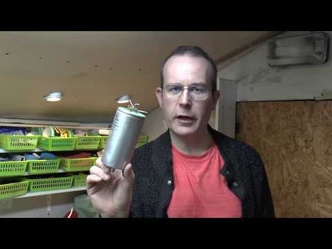
Here is an interesting video on Phase Converter Capacitors:
![]() It may be worth it just spending a little more a let professionals do their job. Unless you are just getting a kick out of this whole process, or it’s your daily job, just get a good quality Rotary Phase Converter from a reputable company, and don’t worry about it.
It may be worth it just spending a little more a let professionals do their job. Unless you are just getting a kick out of this whole process, or it’s your daily job, just get a good quality Rotary Phase Converter from a reputable company, and don’t worry about it.
I hope this helps some of you. Enjoy

Click on the white button above to find your electrician!

Our Team

Legal Disclaimer