
![]()
How to Wire a 4 Way Switch [with Diagrams and PDF]
DISCLAIMER: AS AN AMAZON ASSOCIATE I EARN FROM QUALIFYING PURCHASES. THIS POST CONTAINS AFFILIATE LINKS THAT WILL REWARD ME MONETARILY OR OTHERWISE WHEN YOU USE THEM TO MAKE QUALIFYING PURCHASES. FOR MORE INFORMATION, PLEASE READ MY EARNINGS DISCLAIMER. |
It is always a good idea to regulate lighting in large open spaces, where people come in and come out all the time. The same goes for the stairs. Multiple light switches should definitely be employed along the stairwell on each and every floor.
Even if you would like to have ten switches to control one light (as an example), you will need two 3-way switches and eight 4-way switches. But don’t forget that all 4-way switches should go in between the two 3-way switches.
All additional 4-way switches get connected in between 3-way switches as well. This kind of arrangement is very convenient for bigger spaces with several doors.
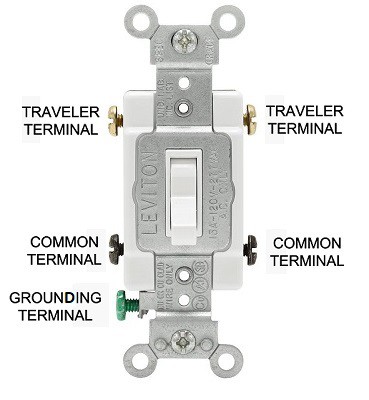
What is a 4-way switch? A four-way switch is a special complex device that is composed of 5 screws (or terminals) in total, which include: (2) common terminals, (2) traveler terminals, and (1) ground terminal:
If you compare this switch to other variations, the 3-way switch will have four screws (or terminals) and the 2-way (casual/normally used “single-pole” switch) will have only three screws (or terminals).
4-way switch screws (or terminals) are usually color-coded, which includes:
- Two brass-colored screws (or terminals): “Traveler terminals”.
- Two dark (or black)-colored screws (or terminals): “Common terminals”.
- Green-colored screw (or terminal): “Ground terminal”.
4-way switches are generally used for controlling the light from three or more switches or locations (could be each floor of the stairs, for example). These switches are employed in circuits along with the linked 3-way switches.
In a 4-way switch, a total of four screws (or terminals) are present to provide 2 sets of toggle locations. These toggle locations will allow the current to use two pathways by which it can pass.
When the switch is placed in the upward position, the current will flow through one set of terminals and when it is placed in a downward direction, it will pass through another set. In order to figure out which terminals are linked, you can use an ohmmeter (or multimeter) for testing.
This process is described in a better way, below (video):

![]()
Wiring a 4-way switch setup
Before starting to wire a 4-way switch setup, you must take account of some of the warnings:
** Warning #1! Connecting wires may look simple, but if you make the slightest mistake, you will put yourself into a dangerous situation that could end up being fatal. If you are not sure about what you are doing, ask a professional for assistance.
** Warning #2! Disconnecting wires from the main power source is a must and is the first thing you should do before anything else. Just flip the appropriate breaker switch and only then you can start working with wires.
Wiring for a 4-way switch is not difficult to accomplish if you avoid some basic mistakes (one of which is connecting the wrong wires that come from 3-way switches into a 4-way switch). The reason why this is a problem is that you can do a very logical and obvious thing, but your light will not turn on.
What am I talking about? The wires that are in your white cable (that connects the switches) are color-coded. The terminals (or screws) of the switch are color-coded as well.
The basic 4-way switch setup includes 3 switches:
- Two 3-way switches
- One 4-way switch
There could be more 4-way switches involved, but in this setup, we will connect one 4-way switch in between two 3-way switches.
Wiring problems
Once you take out the wires from the cable and start connecting them, you may end up with red (traveler) wire going to the brass-colored screws (or terminals) and black (hot) wire to the black (or dark) colored screws (or terminals).
Why? Because this is logical, but NOT the right way to do it (light will not work).
In order for the light to work properly, you have to install both wires (red and black) from the first 3-way switch on the brass screws (or terminals) and the same colored wires (red and black) from the second 3-way switch – on the dark (or black) screws (or terminals).
The rest is quite simple (assuming that the first 3-way switch is connected already). If it’s not, feel free to read this article on connecting 3-way switches. In order for our light arrangement to work, all is left to do is to connect white (neutral) wires, that come from both 3-way switches, together and connect both of the ground wires as well (while leaving a little piece to have it connected to the 4-way switch.
Here is a video on how to do it (better to see once, than to hear twice):

![]()
Can you use a 4-way light switch for more than 3 locations? Sure! Connect them all and be comfortable shutting your lights on and off from any part of the kitchen (for example).
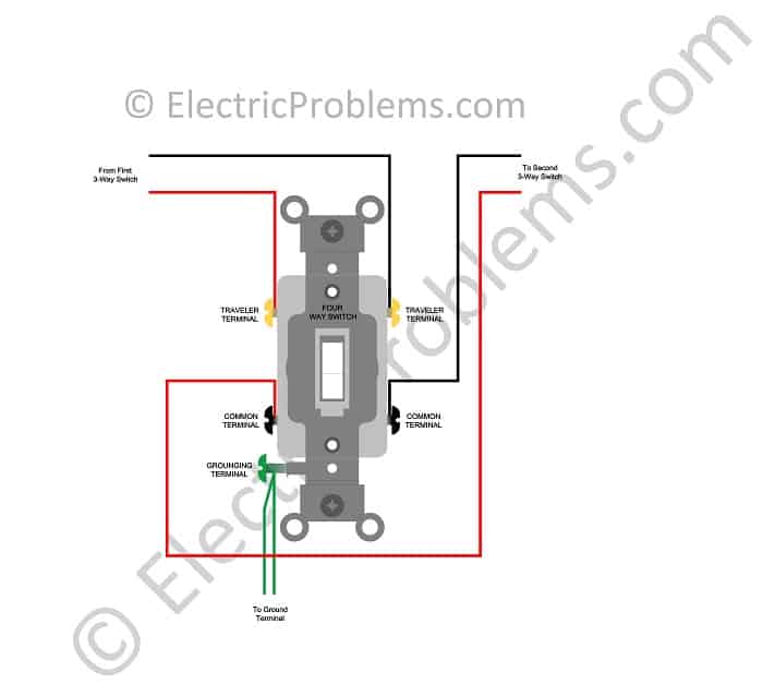
Connecting the terminals of a 4-way switch
Neutral (or white) wires of three-way switches should be connected together and also the ground copper wire (that is attached to the green terminal on the 4-way switch). Now you will have only red and black (or hot) wires left.
The wires from the first 3-way switch should be connected to the brass terminal (doesn’t make a difference which one to which side) and the second 3-way switch should be connected to the dark set of terminal screws.
Here is a graphical illustration of wire connections at the 4-way switch:
4-way switch wiring diagram (Single Light)
The general wiring of the 4-way switch is explained well in the video below:

![]()
Here are different ways to wire a 4-way switch (two basic setups):
- The power is coming into the light fixture first.
- The power is coming into switches first.
4-way switch wiring diagram power at light
Now, let’s go over this type of setup:
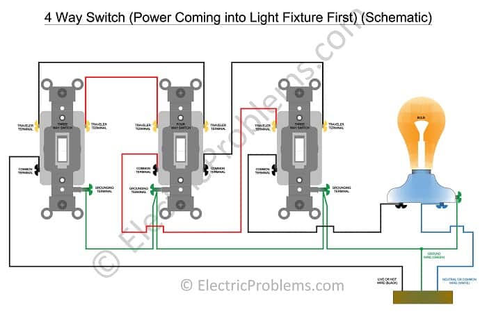 | 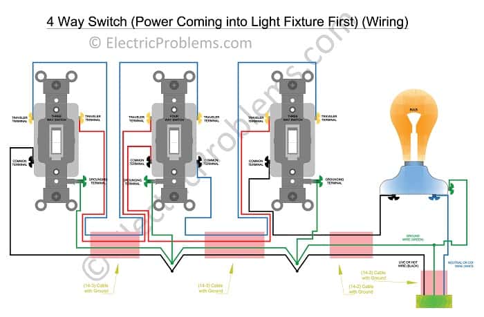 |
We are including PDF files, so you can see the picture in greater detail (schematic & wiring).
In the picture given above, a 14-2 cable (2 wires with the ground) is being used and it is running from the light fixtures to the three-way switch. A Three-wire cable with the ground (or 14-3 cable) is employed to take power to the 4 way switch and another 14-3 cable is used for connecting the last 3-way switch where the circuit ends.
4-way switch wiring diagram power at the switch
This setup can be categorized as:
- Power is coming to the first 3-way switch first
- Power is coming to the 4-way switch first
- Power source and light is connected to the same 3-way switch
Case #1. Power coming to the 3-way switch first.
Now, let’s take a look at schematics, where power is coming to the 3-way switch first:
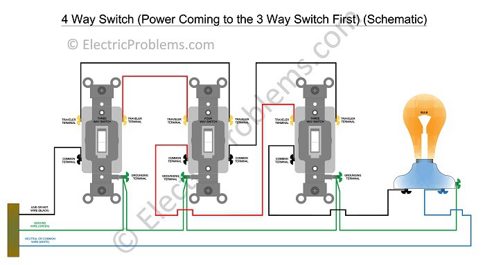 | 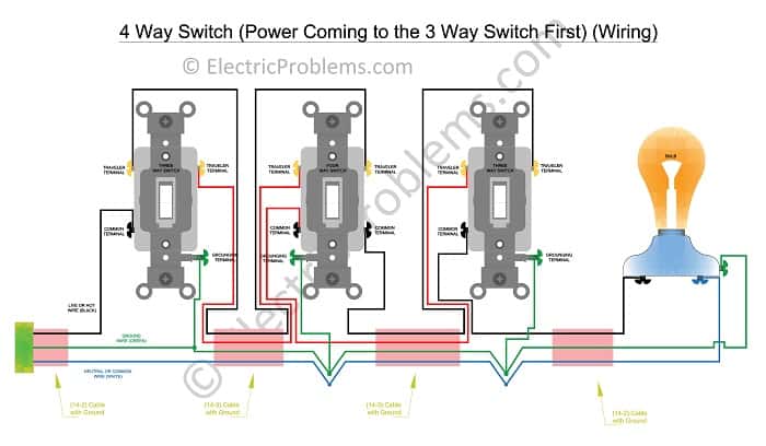 |
Here are PDF files of these diagrams (schematics & wiring).
In this case, there is a 14-2 cable running directly from the source of power to the 3-way switch, and a 14-3 cable is employed to run till the 4-way switch. After that one more 14-3 cable is employed for connecting the 4-way switch to the second 3-way switch and then, finally, the 14-2 cable is used for connecting with the light or multiple fixtures (in case of multiple lights).
Case #2. Power is coming to the 4-way switch first.
Now, let’s take a look at schematics, where power is coming to the 4-way switch first:
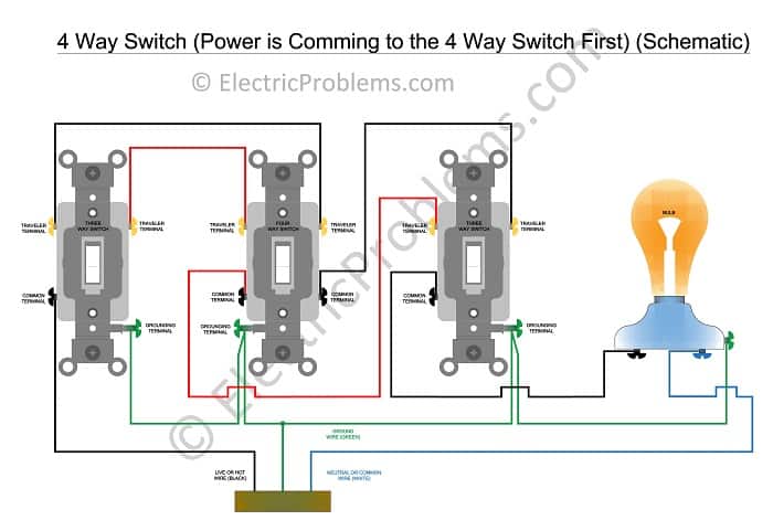 | 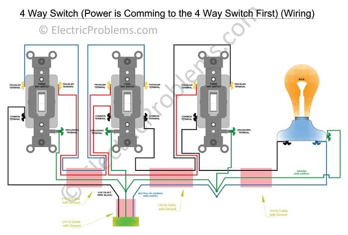 |
Here are the above diagrams in PDF format (schematics & wiring).
In this case, a 14-2 cable is used to power the 4-way switch fixture first. Then, there are two 14-3 cables leaving the 4-way switch fixture (one 14-3 cable going to the first 3-way switch and the other one to the second 3-way switch). After that, a 14-2 cable is used to connect the second 3-way switch to the light fixture.
Case #3. The power source and light are connected to the same 3-way switch.
Now, let’s take a look at schematics, where power and light source are connected to the same 3-way switch:
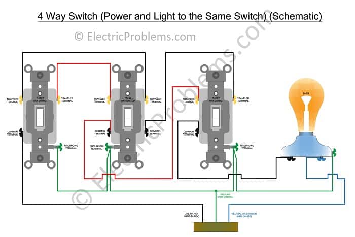 | 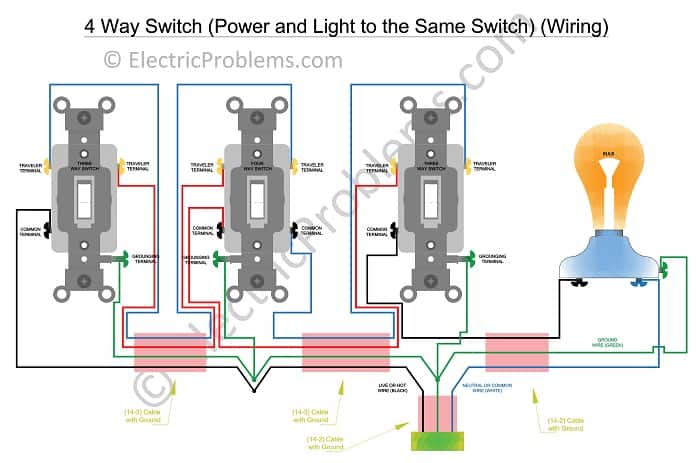 |
For more detailed diagrams, check out PDF files (schematics & wiring).
In this case, a 14-2 cable is used to power the second 3-way switch fixture, first. Then, there are two cables leaving the second 3-way switch fixture (one is 14-2 cable, which is used to power the light fixture and the other one is 14-3 cable, which is used to connect the second 3-way switch to the 4-way switch). Then, a 14-3 cable is used to connect the 4-way switch to the first 3-way switch and that ends the circuit.
Feel free to download all schematics in PDF format.
4-way switch wiring diagram multiple lights
If you need multiple lights attached to this system, just connect them together (white wire to white wire and black to black). Here is an article to help you with wiring a 4-way switch with multiple lights.
Also, never underestimate the awesome power of Smart switches (3-way), which make our life a whole lot easier 😊 …

Click on the white button above to find your electrician!

Our Team


Legal Disclaimer

