
![]()
3 Way Switch Wiring Diagrams [with PDF]
DISCLAIMER: AS AN AMAZON ASSOCIATE I EARN FROM QUALIFYING PURCHASES. THIS POST CONTAINS AFFILIATE LINKS THAT WILL REWARD ME MONETARILY OR OTHERWISE WHEN YOU USE THEM TO MAKE QUALIFYING PURCHASES. FOR MORE INFORMATION, PLEASE READ MY EARNINGS DISCLAIMER. |
Wiring your 3-way switch should not be complicated if you have diagrams that you can use (you may want to print some out as well). It is also a good idea to watch some videos prior to installation to avoid unnecessary problems.
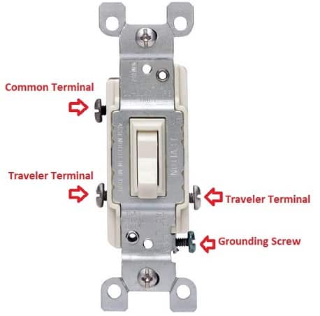
Before we get to wiring diagrams, here is how the 3-way switch terminals are color-coded:
- Green for Ground Terminal.
- Brass color for Traveler Terminals.
- Black for Live (or Hot wire).
And this is what you will need for 3-way switch wiring:
- Wires
- Black (Live or Hot Wire)
- Green (Ground Wire)
- White (Neutral or Common Wire)
- Red (Terminal Wire)
- Two 3-way switches
- Light bulb
- 3-wire cables and 2-wire cables
- Switch box
- Wire connectors
- Ceiling box
The diagrams for 3-way switch wiring I broke down into the following sections (see below):
- Light after switches. The power source is coming to a light switch first.
- Light before switches. The power source is coming to light fitting first.
- The electricity source and light fixture are connected to the same switch.
- The electricity source and light are in between switches.
Diagram #1. Light after switches (power at the switch).

Here is a schematics in PDF format and a step-by-step process of connecting the wires with power at the switch:
- Step 1: Connect live (or a hot wire) to the common (or black) terminal of the first switch.
- Step 2: Use black and red wires to connect traveler (or brass-colored) terminals of the first switch and the second switch. It doesn’t make any difference if it’s in parallel or in cross positions.
- Step 3: Connect the common (black) terminal of the second switch to the bulb through the ceiling box.
- Step 4: Connect the incoming white (neutral) wire to the other light fitting terminal.
- Step 5: Ground wires connect with the ground (green) terminals of both switches and also with the bulb ground fitting terminal (or common all ground terminals through green wires). The ground wire is used for safety purposes.
If both switches are in the same positions (like both are “ON” or both are “OFF”), then there will be no flow of electrons (the path will be open and the bulb will not glow). On the other hand, if one switch will be “ON” and others will be “OFF” then electrons will be flowing (the path will be closed and the bulb will glow).
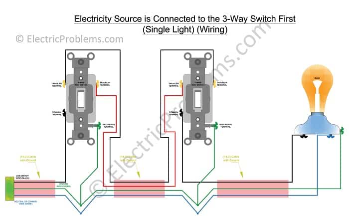
You can download the PDF file here to see more details. On the wiring diagram above we have:
- Two-wire cable as an electricity source.
- Three-wire cable between switches.
- The two-wire cable between the second switch and a light fixture.
Electricity in this circuit travels through the hot wire across the first switch and through the traveler wire to the second switch. If the second switch is in the “OFF” position, then the light will be off, it’s in the “ON” position, then the light will come on.
After the light came on, electricity comes back through the neutral (white) wire. If we flip switch number one, the circuit will be broken and the light will turn off.
Diagram #2. Light before switches (power at light fitting).

Below is a step-by-step process of connecting the wires with power at the light fitting (download PDF file for greater detail):
- Step 1: Bring the hot black wire from the power source to the common terminal (black) of the second switch through the ceiling box.
- Step 2: Now we will connect black and red wires to the traveler terminals of the switch (which are color-coded in brass color). They could be in parallel or in crossed positions.
- Step 3: Connect the common (black) terminal of the first switch to the light fitting terminal through the ceiling box.
- Step 4: The incoming white (or neutral) wire should be connected to the other light fitting terminal.
- Step 5: Connect ground wires to the green (or ground) terminals of both switches and the ground fitting terminal of the light bulb.
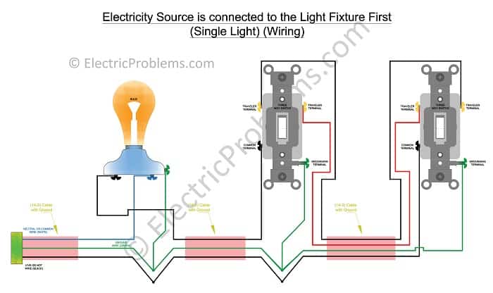
Here is a downloadable PDF file for you! In the above diagram, the power from the electricity source is coming through a two-wire cable to the first switch. Three-wire cables are used between the two switches.
As we power this circuit, electricity will flow through the hot wire over to the second switch. As it goes through the red traveler, it will stop at switch number one.
When we flip the second switch, the electricity can now go through to the light fitting and make it back through the neutral (or white) wire. When we flip the first switch, electricity can’t make it past the switch and the light is off.
In order to turn the light back on, you need to flip the second switch again and the circuit will be complete.
Diagram #3. The electricity source and light fixture are connected to the same switch.
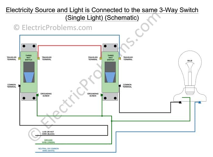
Feel free to download a PDF file of the diagram above. In the step-by-step process below, we will be connecting the wires to the power source and the light fitting attached to the same switch:
- Step 1: Carry the hot black wire from the power source to the common terminal of the first switch.
- Step 2: White and red wires get connected to the traveler (brass color) terminals to the switch. You could use either terminal.
- Step 3: The common terminal (color – black) of the second switch gets connected to the light fitting terminal via the ceiling box.
- Step 4: Link the incoming white (or neutral) wire to the other light fitting terminal.
- Step 5: Ground wires get connected to the ground terminals of both switches (which are color-coded in green) as well as to the bulb ground fitting terminal.
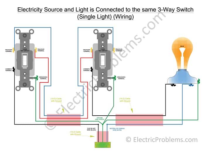
We are including PDF files for printout and reference. To wire the circuit in this way you will require the following cables:
- Three-wire cable in between switches.
- Two-wire cable as an electricity source.
- The two-wire cable goes between the second switch and a light fixture.
If the second switch is in the “OFF” position, the light will be turned off, if it is in the “ON” position, the light will be switched on.
In this circuit, electricity goes through the hot wire to the first switch and then, to the second switch through the traveler wire. As it gets to the second switch and it is “OFF” position, electricity will stop there, and there will be no light.
On the other hand, if the second switch is in the “ON” position, then electricity will go through and you will have light. The power goes back into the neutral (white) wire until the light comes on.
This situation is somewhat close to the first circuit where the power is on the switch.
Diagram #4. The electricity source and light are in between switches.
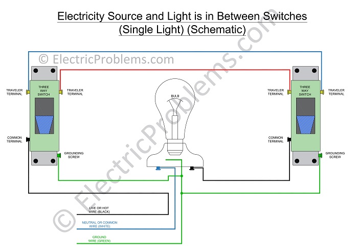
A more detailed diagram is included in this PDF file. The step-by-step process of connecting the wires with the power source and light fitting between the light switches can be seen below:
- Step 1: Carry the hot black wire from the power source to the common terminal of the first switch.
- Step 2: Use white and red wires for connecting to the ceiling box the traveler (or brass color) terminals of the switch. Either terminal will work.
- Step 3: Carry the incoming neutral (white) wire through the ceiling box to one of the light fitting terminals.
- Step 4: Carry another neutral (white) wire from the other light fitting terminal to the common terminal of the second switch via the ceiling box. Label both ends of this wire with black electrical tape to indicate that it’s hot.
- Step 5: Both switches (green terminals) and a light bulb (ground fitting terminal) get connected through a green wire.
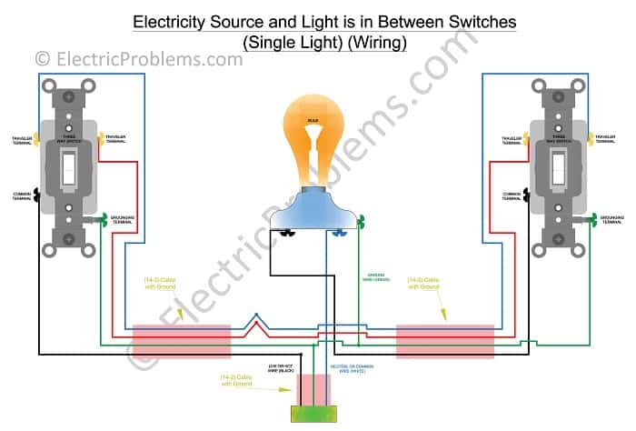
Here is a more detailed PDF file. To wire this circuit, you will need the following cables:
- Three-wire cable between switch one and the light fitting.
- Two-wire cable as an electricity source.
- Three-wire cable between the light fitting and the second switch.
In this case, electricity flows through the ceiling box from the first switch to the second switch. The circuit is disrupted at the second switch, so the light is turned off.
When the second switch is flipped “ON”, the power will run into the switch and the light, as well as into the neutral (white) cable while turning the light on. If the first switch is turned (or flipped “OFF”), the electricity still makes it to the second switch through the red traveler, but the circuit is broken again.
If the second switch gets turned “ON” again, the circuit becomes complete and the light is turned on.
3-way switch wiring
So, how do you wire a three-way switch? Here is a nice video to help you out:
![]()
For the multiple lights version, please visit this page (How to wire a 3-way switch with multiple lights). Now you can download all the PDF files of the above diagrams!
Ready to wire your 3-way switch? Here are some simple switches (paid link) that I found on Amazon.
And if you are like me, “Bowing to the God of Smart Apps”, you will probably want to get one of these (paid link)! And here are some light bulbs (paid link) that go with them.
No more getting up to shut the light down!

Click on the white button above to find your electrician!

Our Team

Legal Disclaimer

